- Home
- District cooling & HVAC
- PICV, balancing & isolation
HVAC & district cooling valves
A chilled-water system needs four valve families. Isolation at plant, risers and terminals. Flow control at each coil, by PICV or balancing valve. Protection by strainers and check valves. Actuation tied to the building management system. Flowsynergy supplies all four from Dubai, with Gulf selection support.
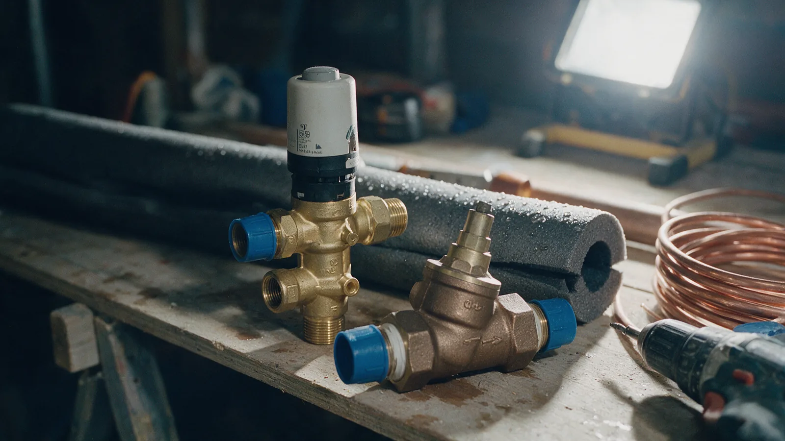
01The valves a chilled-water system needs, plant to terminal
A chilled-water system is a ladder with three rungs. The plant or energy-transfer station makes or receives the water. Mains and risers carry it. Terminals turn it into cooling. Each rung needs different valves. Most field failures are a valve working on the wrong rung.
The ladder names each level's valve family, its job and how it fails. General selection sits under industrial valves. This page covers what changes on chilled water.
Plant room & energy-transfer station
Chillers, heat exchangers, headers and pumps. The largest valves here, and the ones whose failure stops the building.
Butterfly isolation
- Job
- Isolates chillers, heat exchangers and headers without draining the plant. Wafer and lug patterns stay short and light at DN 200 and above.
- Fails
- A liner left part-open to throttle erodes. A plain wafer valve on a dead-end line is the classic plant-room mistake. Specify a lugged valve rated for dead-end service.
Check valves
- Job
- Stops reverse flow through parallel pumps and keeps a tripped pump from spinning backwards.
- Fails
- Slam on pump trip, when the disc closes slower than the flow reverses. Tall risers need a silent or spring-assisted pattern.
Strainers & dirt control
- Job
- Catches installation debris before pumps, heat exchangers and control valves. Air and dirt separators keep the closed loop clean.
- Fails
- A screen never blown down becomes the largest pressure drop in the plant room.
Distribution & risers
Sectional isolation so one floor can be worked on. Branch balance so no riser starves another.
Sectional isolation
- Job
- Sections the network floor by floor: butterfly above about DN 100, gate where a straight full bore matters, ball below about DN 50.
- Fails
- Any isolation valve left part-open to “balance” a branch. No flow characteristic, no repeatable position, no commissioning record.
Branch balancing
- Job
- Double-regulating valves set branch proportions and give the commissioning engineer a measurable differential.
- Fails
- A fixed setting is right at one operating point only. Expect drift as terminals modulate. See section 03.
Bypass & differential control
- Job
- Holds minimum plant flow as two-port terminals close. Caps the differential the risers present as pumps turn down.
- Fails
- An oversized bypass that never closes short-circuits supply to return. A permanent low-delta-T machine, billed monthly.
Terminals
Fan-coil units, air-handling coils and chilled beams. Where most selection errors surface.
PICV
- Job
- Holds each coil at scheduled flow across the stated differential-pressure range. Commissioning is a dial setting, not a balancing exercise.
- Fails
- Below its minimum differential the regulator stalls. Debris stalls it faster. Strainer and flushing regime are part of the PICV specification.
Static balancing valve
- Job
- Right at constant-flow terminals, small fixed branches and bypass legs. Set once against the schedule, well below a PICV's cost.
- Fails
- At variable flow an over-supplied coil passes more water at a smaller temperature rise. The warm return is the low-delta-T penalty.
Terminal connection sets
- Job
- Isolation ball valves, strainer, hoses and test points around the coil. One terminal can be serviced without draining the riser.
- Fails
- A connection set ordered without its strainer moves the failure into the PICV cartridge, the most expensive part.
One row per system level. Most chilled-water faults are a device working outside its level.
02Plant and riser isolation: butterfly, gate and ball by size
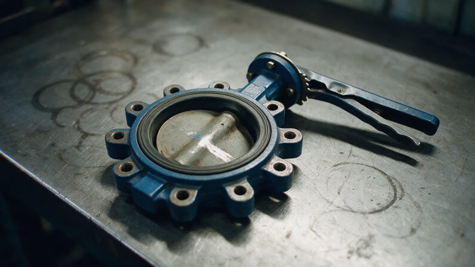
Isolation is a matter of size. Below about DN 50 a ball valve is compact, tight and cheap. From DN 50 to DN 100 the choice opens between ball and butterfly. Above DN 100 the butterfly takes almost everything: lightest, shortest, tight shut-off, economical gearing. Gate valves keep a place where a dead-straight full bore matters: pump suctions and flow-measured lines.
Two plant-room rules repay their space. A wafer butterfly valve cannot hold a dead-end line alone. Where a section opens with the far side live, specify a lugged valve rated for dead-end service. And isolation valves are for isolation: a disc left part-open erodes its liner. The gate vs ball vs butterfly comparison takes it criterion by criterion.
03Terminal flow control: PICV or static balancing valve
Every coil needs its flow held to schedule. Two instruments do the job. A static balancing valve is set once, correct at one operating point. A pressure-independent control valve regulates continuously: its cartridge removes the network's pressure swings, so the coil sees scheduled flow at every load. On a variable-flow network the PICV is the default. Static valves suit constant-flow branches and bypasses.
The Gulf sharpens the choice. Cooling runs year-round, so a system out of balance never gets an off-season reset. High-rise differentials between plant floor and roof are what a static setting cannot follow. District-cooling tariffs bill low return temperatures directly. The full case is the PICV vs balancing valve comparison, with system context in the district cooling & HVAC guide.
04Mechanical versus electronic PICV: where each belongs
A mechanical PICV regulates with a diaphragm and spring. The actuator only drives the control port. An electronic PICV replaces the cartridge with a flow sensor and an algorithm, and can report flow and energy to the building-management system. We favour the mechanical cartridge for most terminals. An electronic valve that loses power, signal or sensor loses its flow limit. When a mechanical actuator fails, the regulator keeps working: the coil is over-cooled, not over-flowed.
The electronic valve earns its place where the project needs per-terminal energy metering. Argue the decision on that, not on a data-sheet headline. Either way, flow passes through small ports, which is why section 05 matters here.
05Protecting the loop: strainers, check valves and dirt management
A chilled-water circuit is closed. Whatever is in it at handover stays in it: weld slag, joint compound, sand, then magnetite from corrosion. The damage happens at the smallest ports: PICV cartridges, control-valve seats, heat-exchanger passages. Protection is layered. Strainers sit before pumps, heat exchangers and every terminal device, with mesh chosen for the device protected. Air and dirt separators remove what strainers pass. Check valves on pump discharges stop reverse rotation.
The cheapest protection is procedural. Flush and treat the water before a single PICV is installed. Pull and inspect strainer screens after the first weeks. The alternative is familiar: a stalled cartridge returned as “faulty”, full of construction debris. Screen inspection is part of the technical support we quote with the valves.
06Selecting by service condition
Four figures from the schedule drive the selection. Temperature is undemanding on chilled water. The elastomers do the work, and must be rated for the supply temperature. Differential pressure decides the PICV twice: available ΔP at the index terminal must exceed the stated minimum, and ΔP at the terminal nearest the pumps must stay under the maximum. Both come from the data sheet for the exact model. Glycol raises viscosity and shifts every flow chart, so state type and concentration on the enquiry.
Building height sets static pressure, and static pressure selects body ratings. A valve at the base of a tall riser carries the full column head before the pumps add anything. That pushes plant-room bodies from PN 16 toward PN 25. Materials follow the water: dezincification-resistant brass or bronze in threaded sizes, ductile iron or steel flanges beyond.
Reference values. Confirm against the current edition of the standard and the manufacturer's rating table.
07Low delta-T and its valve causes: oversizing, authority and bypass
Low delta-T is the district-cooling disease. The building returns water barely warmer than it received, and pays for flow it never turned into cooling. Dubai operators such as Empower bill for exactly that. It is usually called a controls problem. It is mostly a valve problem, with three mechanical causes.
Oversizing: a valve a size too large runs nearly closed, controls poorly and overshoots the moment it cracks open. Authority: a two-port valve whose pressure drop is small against the circuit's behaves like a switch. Holding authority is what the PICV's regulator is for. Bypass: any path that lets supply water reach the return without crossing a coil dilutes the return. Fix the three and the return temperature comes back.
08Governing standards and test references (confirm the current edition)
Hydronic valves answer to two kinds of document: rating standards, and commissioning codes that say how flow is set and proved. Every designation below is defined in the glossary.
| Designation | What it fixes | Kind |
|---|---|---|
| BS 7350 | Double-regulating globe valves and flow-measurement devices for heating and chilled water. The balancing valve's design document. | Design |
| CIBSE Commissioning Code W | Commissioning method, proportional balancing and flow verification. | Method |
| BSRIA BG 2 | The practical procedure and the tolerances on measured flow. | Method |
| ASHRAE Handbook: HVAC Systems and Equipment | Valve authority, variable-flow design and the case for pressure-independent control. | Reference |
| EN 1092-1 / ASME B16.5 | Flange dimensions and PN or class ratings for the flanged sizes. | Ends |
| EN 12266-1 / ISO 5208 | Pressure testing of metallic valves: shell test and seat-leakage rate for the isolation function. | Test |
| ASME B16.34 | Pressure/temperature ratings for the steel-bodied sizes, read against the material group. | Ratings |
| EN 10204 | Inspection document types for body materials: 2.2 non-specific, 3.1 mill-certified. | Document |
09Commissioning documentation to request
A valve package is complete only with the paper that lets it be commissioned. Ask for the five items below with the quotation. The sourcing & documentation guide explains each one.
Flow-setting chart
The dial-to-flow table for the exact model and size, with the valid differential range. The document most often missing on commissioning day.
Minimum and maximum ΔP statement
The differential below which the regulator stops regulating, and above which the valve is out of rating. Both figures belong on the terminal schedule.
Commissioning record
Measured flow at a sample of terminals against the schedule, within tolerance, recorded with every valve's setting.
Pressure-test record
Shell and seat test to EN 12266-1 or ISO 5208 on the isolation valves. State pressure, medium and duration, not simply “passed”.
Material certificate
EN 10204 2.2 or 3.1 for the bodies. Dezincification-resistant brass or bronze named as such where the water demands it.
10Product lines for HVAC and district cooling
Specify the duty first. Send the medium, pressure, temperature, size and quantity. View our trading brands or ask our Dubai team to confirm a suitable product.
 KITZIndustrial valves
 DFTCheck valves
 EtelecElectrical connection protection
 KVC UK LtdIndustrial valves
 VogtIndustrial valves
Enquiry Dubai
Send the terminal schedule and the system level, not a part number.
State the system level: ETS, plant room, riser or terminal. Give the design flow, available differential pressure, temperatures and pipe size. We reply with the valve family, size and setting, and the documents to match.
Send an enquiry