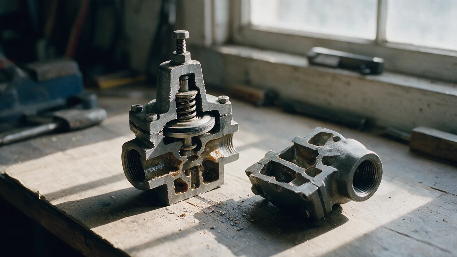
The protection chain: strainer → reducing valve → safety valve → trap
Steam protection is one chain, selected in sequence. Each device handles what the previous one lets through. The strainer protects the reducing valve's pilot. The reducing valve sets downstream pressure. The safety valve covers the day that valve fails open. The trap removes condensate. Size any link on pipe diameter and the chain protects nothing. The method behind it is in valve selection by standard and service condition.
- Strainer
Ahead of every device with small passages. Mesh per the manufacturer; blowdown on the schedule.
- Pressure-reducing valve
Sized on required flow at the inlet and outlet pressures, never on pipe size.
- Safety valve
Set and sized to relieve the reducing valve's full failed-open flow, downstream of it.
- Steam trap
Chosen by application (drip leg, exchanger, tracing) at the real condensate load and ΔP.
The sizing variables: what governs each device
Every device has one governing variable. Every common failure is a device sized on the wrong one. The sections after the table take the devices in turn.
| Device | Governing variable | What happens when it is wrong |
|---|---|---|
| Pressure-reducing valve | Required flow at the stated inlet and outlet pressures | Oversized on pipe size, it hunts, cycles downstream pressure and wire-draws its seat |
| Safety valve | Relieving capacity at set pressure, at least the PRV's failed-open flow | Undersized, the downstream line overpressures on the day the PRV sticks open |
| Steam trap | Condensate load with a start-up factor, at the working differential pressure | Wrong type or size: the exchanger waterlogs and hammers, or the trap blows live steam to the return |
| Strainer | Mesh matched to the protected device's clearances | Too coarse and the pilot blocks; too fine without blowdown and the strainer starves the line |
| Check valve (condensate) | Minimum flow that holds the disc fully open | Line-sized by reflex, the disc flutters at part load and hammers on pump trip |
Pressure-reducing valves: direct-acting versus pilot-operated, and turndown
A direct-acting reducing valve balances downstream pressure against a spring across a diaphragm. Simple, compact and dirt-tolerant, but accuracy droops as flow rises, so it suits small loads. A pilot-operated valve loads the main diaphragm from a small pilot. It holds set pressure nearly flat across the flow range, with tighter shut-off. That is the process standard, at the price of small passages needing a clean, strained supply. A single valve spanning a 10:1 range hunts at the bottom of it, so wide loads take two staged valves. The working-through is in how to size a pressure-reducing valve, with principles in Spirax Sarco's steam engineering tutorials.
Safety valve versus relief valve: what each term means
The two words are used interchangeably in enquiries, but mean different devices in the codes. A safety valve pops: it opens fully at set pressure with a rapid lift, which is what compressible fluids need. Steam and gas duties take safety valves. A relief valve opens in proportion to the overpressure, which is what liquids need. Vessel overpressure protection is governed by ASME BPVC Section VIII in ASME jurisdictions, and by the corresponding EN codes elsewhere. Name the governing document in the enquiry.
Reference values: confirm against the current edition of the standard and the manufacturer's rating table.
Saturated steam couples temperature to pressure
For saturated steam, pressure fixes temperature. The two are one variable, tabulated in the steam property formulations published by IAPWS. Saturated steam at 10 bar g is about 184 °C, so every device in the chain must be rated for the temperature its pressure implies. This is also why reducing pressure is worth doing: lower-pressure steam is cooler and carries more latent heat per kilogram. It cuts the other way too. A reducing valve that fails open exposes the downstream line to upstream temperature as well as pressure.
Reference values: confirm against the current edition of the standard and the manufacturer's rating table.
Sizing the safety valve for the reducing valve's failed-open capacity
The sizing case is not the normal load. It is the worst credible failure: the reducing valve jammed fully open. The safety valve must relieve the flow that valve passes wide open at full upstream pressure, read from its datasheet, not from process demand. Set pressure sits above the reduced pressure, with margin so normal control never lifts the valve, and below the downstream design pressure the code protects. Change the reducing valve and the safety valve's sizing case changes with it.
Steam traps by application: drip legs, process heat exchangers, tracing
Traps are chosen by application first, mechanism second. Drip legs on steam mains collect small, steady loads: a thermodynamic disc trap is compact, robust and tolerates superheat and water hammer. Process heat exchangers make large, swinging loads that must drain instantly: a float-thermostatic trap discharges continuously at any pressure and vents air at start-up. Tracing wants a small thermostatic trap that holds condensate back to use its sensible heat. Two rules travel across all three. Never let one trap drain two loads. Size on the real condensate load with a start-up factor, at the actual differential to the return. The selection ladder is in the steam trap selection guide.
Strainers, dirt and the pilot that never stood a chance
Steam mains carry mill scale, jointing compound and rust. The first small passage downstream collects it. A Y-type strainer ahead of every reducing valve, trap and control valve is the cheapest component in the chain, and the one most often omitted. Fit the mesh the device manufacturer specifies, finer for pilot-operated valves than for traps. Mount the pocket horizontally in steam lines. Put blowdown on the maintenance schedule: a strainer never blown down becomes an obstruction.
Water hammer: where it comes from, and what prevents it
Water hammer is condensate travelling at steam speed until it meets a fitting. The causes are drainage causes: un-drained low points, dead legs, traps that back up, pockets where a main sags. The cures are selection cures: drip legs with traps at every riser base, float traps on loads that must drain instantly, non-slam checks on condensate pumps, and a separator where the supply is wet. A chain that hammers is telling you where the condensate stands.
Worked example: a reducing station feeding a heat exchanger
A jacketed process vessel needs steam at 3 bar g; the plant main runs at 10 bar g saturated. In flow order: isolation valve, separator and trap set to dry the supply, Y-type strainer, then a pilot-operated reducing valve sized for the exchanger's flow at 10 → 3 bar g and checked for turndown across the batch cycle. Then a safety valve sized for that valve's failed-open capacity, set between 3 bar g and the jacket's design pressure, discharging to a safe location. The exchanger drains through a float-thermostatic trap sized on the batch condensate load with a start-up factor. Every capacity traces to a datasheet figure at a stated condition.
Governing standards and the “confirm against the current edition” rule
Bodies and flanged ends are rated under ASME B16.34 and ASME B16.5. Shell and seat tests report to API 598 or ISO 5208. Pressure-retaining parts carry EN 10204 inspection documents. Steam properties come from the IAPWS formulations, and overpressure protection follows the pressure-vessel code that governs the plant. Set pressures and capacities are confirmed against the manufacturer's datasheet for the exact model. The glossary unpacks each document.
Reference values: confirm against the current edition of the standard and the manufacturer's rating table.
Buyer mistakes: the valve that hunts, and the relief valve the pipe cannot feed
The first mistake is buying the reducing valve on price and pipe size. Oversized to match the line, and direct-acting because it was cheapest, it hunts. Pressure cycles, the seat wire-draws, and the saving is repaid in a valve replaced within the year. The second mistake is treating the safety valve as an accessory. Sized on the nominal load rather than the failed-open case, it is a certificate on a bracket, not protection.
A reducing station is bought once and paid for every shift it runs. A cheap valve does not remove the cost of accuracy, drainage and protection. It moves that cost into scrapped batches, hammering pipework and unplanned shutdowns.
Documentation to request with the quotation
For a protection chain, the paperwork is part of the device:
- Capacity charts for the reducing valve at the stated inlet and outlet pressures, and its failed-open flow.
- Set-pressure test certificate and rated relieving capacity for the safety valve, naming the governing code.
- Trap capacity at the working differential, and the recommended strainer mesh for each device.
- Material certificates to EN 10204 and test reports to API 598 / ISO 5208 for the isolation valves in the station.
What each certificate proves is covered in sourcing and documentation.
Related pages and the next step
Specify the duty first. Send the medium, pressure, temperature, size and quantity. View our trading brands or ask our Dubai team to confirm a suitable product.
Related: Industries we supply.