What does ISO 5211 standardise?
ISO 5211 sets out how a part-turn actuator, with or without a gearbox, is attached to an industrial valve. ISO's own summary of the current edition, ISO 5211:2026, lists three things it fixes: the flange dimensions for mounting the actuator on the valve or on an intermediate support, the dimensions of the actuator's driving component, and reference torque values for joints and couplings built to those dimensions.
It is an interface standard, so it settles fit and not duty. It does not tell you what torque the valve needs to turn, what the actuator can deliver, or whether either suits the medium. Those come from the valve and actuator data sheets. The four questions that size an actuator are on actuators, dampers and pipeline fittings, and choosing the valve itself comes first, in valve selection.
ISO also draws two boundaries. Fixing an intermediate support, such as a bracket or spool piece, to the valve is outside the standard, so a bracketed assembly is only half covered. And on control valves, attachment to ISO 5211 applies only where the supplier and the purchaser have agreed it, so it should not be assumed on a control valve line item.
What does the F number in F05, F07 or F10 mean?
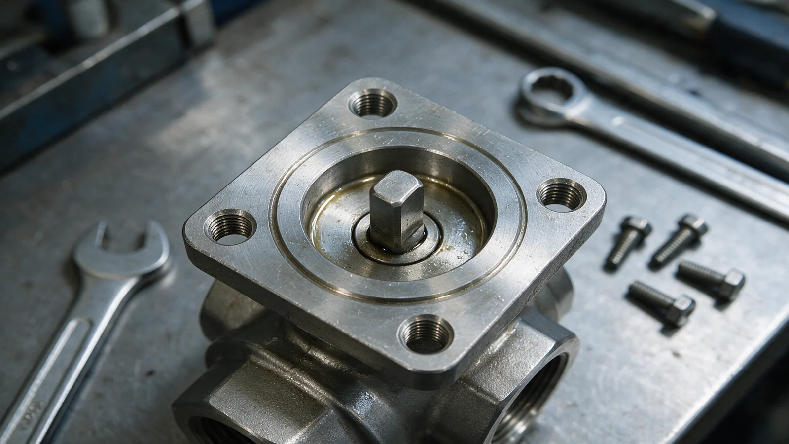
The F number is the flange designation, and it names a whole family of dimensions for the mounting pad rather than a single one: the bolt circle, the size and number of the fixings, the centring recess, the flat landing area the fixings bear on, and the depth of the tapped holes. A valve marked F07 and an actuator marked F07 are made to the same pad. A larger F number is a larger pad that can carry more torque across the joint.
The dimensions for each F number are in the standard itself. ISO sells it and its tables are ISO's copyright, so this page explains them rather than reproducing them. For a drawing or a check measurement, work from the purchased edition, or from the valve maker's data sheet, which states the pad the maker machines.
Two features are misread more often than the rest. The bolt circle is what a tape measure finds first, but the reference the actuator locates on is the centring recess machined into the valve flange; the matching spigot on the actuator is optional. And the landing diameter is not the outside diameter of the flange. It is the minimum flat area around the fixings, and outside it each manufacturer is free to shape the flange as it likes.
Is the torque figure for a flange a rating for the valve?
No. The reference torque ISO 5211 gives for each flange is what the bolted joint can transmit under a stated set of conditions: a set stress in the bolts and a set friction between the mating faces. It says nothing about what the valve needs to turn or what the actuator produces.
Most of what changes on site moves the joint away from those conditions. A lower-grade or stainless fastener, a painted mating face or anti-seize on the threads all change how much torque the joint can really carry. Allow as well for torque the steady running figure does not show: inertia in a fast-acting or spring-return actuator can load the pad well above its running torque. Read the flange figure as a ceiling for the joint, not as a margin to spend.
Why do a valve and actuator with the same F number sometimes not fit?
The flange is only one of three things that have to agree. A matching F number settles the bolt pattern; it does not settle the drive, the centring or the edition, and any one of them can defeat a pairing whose pad bolts up perfectly.
- The drive. The standard defines several drive forms, among them keyed shafts, square heads and flat heads, each in more than one size. Two F07 items can carry different drives, and then the stem does not engage.
- The centring. The valve flange carries the recess and the actuator spigot is optional, so an actuator without a spigot centres on nothing and relies on its bolts alone.
- The edition. ISO 5211 has been revised several times. ISO's catalogue lists editions dated 2001, 2017, 2023 and 2026, and revisions have added flange sizes and drive forms, so an old drawing and a current one can describe different interfaces under one F number.
How do you identify the pad already on a valve?
Most buyers meet this standard from the other direction: the actuator has failed, the valve is still in the line, and nobody can find the data sheet. The pad can be read off the valve with a rule and a thread gauge, then matched to its F number in the purchased standard or the valve maker's data.
- Count the fixings and note whether the holes are tapped or plain. A through-bolted pad has clearance holes with no thread in them.
- Measure the bolt circle, centre to centre across opposite holes. It is the most telling single measurement, because each flange size has a different one.
- Measure the centring recess, the machined circular step the actuator spigot drops into, and check that it belongs with the bolt circle you measured.
- Gauge the thread, or the bolt the clearance holes take, and the depth of the tapped holes. A depth shorter than the standard calls for means the pad is not to ISO 5211.
Then read the drive on the valve stem: its form (key, square or flat head) and its size. With the pad and the drive both known, the interface can be written on an order in full.
Does ISO 5211 cover gate and globe valves?
Not for their own attachment. ISO 5211 is the part-turn standard, for valves that go from open to shut in a quarter or half turn, such as ball, butterfly and plug valves. A rising-stem gate or globe valve is multi-turn and carries axial thrust, and its actuator attachment follows ISO 5210, as our actuators page sets out.
The two standards meet at the gearbox. Where a multi-turn actuator drives a separate part-turn gearbox, the assembly has an ISO 5210 joint at one end and an ISO 5211 pad at the other. Dampers sit outside both: the scope says industrial valves, and a damper has no universal pad, which is why the damper section of the actuators page recommends buying damper and actuator as one assembly. Gate, ball or butterfly sets out the valve-type choice itself.
What should an enquiry for an actuated valve state?
An actuated valve is two purchases that have to arrive as one assembly. Four lines settle the interface, which is what this page covers; the torque, duty, fail position and signal that size the actuator are the questions on the actuators page, and they belong in the same enquiry.
- The flange type, as marked, as measured by the four steps above, or as confirmed from the valve maker's data.
- The centring: the recess the valve flange carries, and whether the actuator has a spigot.
- The drive form and its size, named on the line item rather than assumed from the flange type.
- The edition of ISO 5211 the specification cites, and any non-standard interface that has been agreed.
Writing those four on the line item is what stops an actuated valve arriving as two boxes that will not mate. The certificates the purchase order needs are a separate list, set out in valve documentation a buyer should demand, and the glossary entry for actuator covers the terms used here.
Flowsynergy Solutions Limited supplies valves, actuators and fittings from Level 41, Emirates Towers, Dubai, with valve selection and technical support. Send the line item with the pad details it names, and read technical support and testing for how we work. Or call +971 4 313 2786, Monday to Friday, 8:30 am to 5:00 pm Dubai time.
Questions buyers ask about ISO 5211
Is a higher F number always better?
No. A larger pad costs more, weighs more and makes the assembly bigger, and all it buys is torque capacity at the joint. The right pad is the smallest one that clears the valve's required torque with the agreed safety factor, not the largest one the quoted actuator happens to fit.
Does the actuator have to have a spigot?
No. ISO 5211 puts the centring recess on the valve flange and makes the spigot on the actuator optional. Because the two can differ, state on the enquiry whether the actuator has one, so the pair is settled in writing.
Can an adaptor bracket join a mismatched valve and actuator?
It can, and it adds two unknowns: a second bolted joint whose torque capacity nobody has calculated, and bolt lengths the original tapped depths were not chosen for. Attaching an intermediate support to the valve is also outside ISO 5211, so the standard cited for the bracket does not cover the part that carries it.
Which edition of ISO 5211 applies?
The one your specification cites. ISO's catalogue lists editions dated 2001, 2017, 2023 and 2026, and the 2026 edition, published in February 2026, replaced the 2023 one. Revisions have added flange sizes and drive forms, so an older drawing and a current one can describe different interfaces at the same F number.
Does ISO 5211 say anything about actuator performance?
No. It is an attachment standard. It gives reference torques for the joint and the coupling, but it does not rate output, speed, duty cycle or control accuracy. Those are actuator data-sheet figures and must be specified separately.
More on specifying valves and their paperwork is collected in our insights.
Source, read 25 September 2026: ISO's catalogue page for ISO 5211:2026. This page summarises what the standard covers in our own words and does not reproduce its tables or text. Buy the current edition from ISO for dimensions, and confirm every interface against the valve and actuator makers' data sheets.