What a steam trap does, and the three mechanisms that do it
A steam trap is an automatic valve with one duty: discharge condensate and non-condensable gas while holding back live steam. Orifice size, capacity, body material and connection all follow from how it makes that decision. Three mechanisms are in general use. Thermodynamic traps act on the velocity and flash of the fluid crossing a disc. Mechanical traps (float-and-thermostatic and inverted bucket) act on the density difference between water and steam. Thermostatic traps (balanced-pressure capsule and bimetallic) act on temperature, discharging only once the condensate has cooled below saturation. Each mechanism suits a different condensate behaviour, and each fails in its own characteristic way. That is why a trap schedule is written application by application rather than bought as one part number for a whole plant, and it is the reason a cheap trap on the wrong duty is more expensive than the right trap on the first order. Published steam-trapping tutorials group the types the same way. This guide sits inside our steam, pressure and protection cluster; the hardware itself is on the pressure reducing, safety and steam category page.
Trap type, application and failure mode
Read the failure columns as carefully as the application column. A trap that fails open wastes steam quietly for months; a trap that fails shut floods the equipment it was fitted to drain, and that one announces itself in the process.
| Trap type | Suits | Failure mode | How the failure shows |
|---|---|---|---|
| Thermodynamic disc | Steam main drip legs, superheated mains, short tracers | Disc and seat wear; usually fails open | Continuous blow, fast cycling, audible chatter |
| Float-and-thermostatic | Heat exchangers, calorifiers, unit heaters, modulating loads | Float punctures or collapses; fails shut | Exchanger stalls, outlet temperature falls, waterlogging |
| Inverted bucket | Steady loads, dirty condensate, tolerant of back-pressure | Loses its water prime; fails open | Bucket cannot seal, live steam into the return |
| Balanced-pressure thermostatic | Air venting, small loads, tracing that tolerates sub-cooling | Capsule ruptures; most designs fail open | Steam to return, or a cold leg if it fails shut |
| Bimetallic | Long tracers, superheat, freeze-prone outdoor runs | Element fatigues and drifts out of calibration | Backed-up condensate, or a slow steady steam leak |
Thermodynamic traps: drip legs, tracing and the limits
The thermodynamic disc trap has one moving part and no failure mode that floods a line, which is why it is the default on steam main drip legs. It tolerates water hammer, superheat and freezing better than any mechanical trap, mounts in almost any orientation, and is compact enough to sit in a drip pocket. Its limits are equally clear. It needs a real pressure differential to close, so it is a poor choice on low-pressure service, on vacuum, and on any line discharging into a flooded return. It discharges intermittently, in blasts: correct on a drip leg, wrong on a modulating heat exchanger where condensate must leave as fast as it forms. And it cycles: every cycle wears the disc, so a trap oversized for its load cycles faster and wears sooner. Oversizing a thermodynamic trap is not a safety margin. It is a shorter service life bought at a higher price.
Float-and-thermostatic traps: heat exchangers and continuous discharge
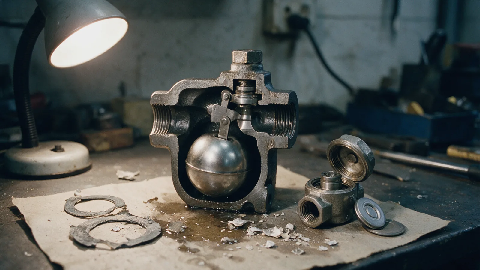
Where the load modulates, the trap must discharge continuously and at saturation temperature, because any condensate held back sits inside the exchanger and takes heating surface out of service. The float-and-thermostatic trap does exactly that: the float rides the condensate level and modulates the outlet, while a separate thermostatic element vents air on start-up. That air vent matters more than most buyers expect. An exchanger full of air on a cold morning heats slowly no matter how good the control valve is. The weakness of the type is that it fails shut when the float is damaged by water hammer or freezing, and a failed-shut trap on a process exchanger is a production problem within the hour. It is also orientation-sensitive and needs protection from debris, so a strainer belongs immediately upstream of every one.
A heat exchanger fitted with the wrong trap rarely announces itself. It simply never quite reaches setpoint on the coldest morning of the year, and someone turns the control valve up.
Why trap selection is a process decision, not a plumbing one
Thermostatic and bimetallic traps: low loads, start-up air and sub-cooling
Balanced-pressure thermostatic traps hold a small sealed capsule whose fill boils just below the saturation temperature of the surrounding condensate, so the trap opens when the condensate has cooled a little and closes as steam approaches. That deliberate sub-cooling is useful where sensible heat can be recovered in the line and unacceptable where the condensate must leave at steam temperature. They are small, cheap, freeze-tolerant when installed to drain, and excellent air vents. Bimetallic traps use a stack of bimetal elements that flex as they heat; they cope with superheat, tolerate freezing and pass large amounts of air on start-up, but they sub-cool much more heavily and drift out of calibration as the elements age. Both types back condensate up the line by design, which is why neither belongs on a drip leg ahead of a control valve.
Differential pressure: what the trap actually sees
A trap is sized on the differential across it, not on boiler pressure. The differential is the pressure at the trap inlet minus the back-pressure in the condensate return, and back-pressure is the sum of return-line friction, the static head of any lift, and the pressure in the flash vessel or receiver at the end of it. Every metre of vertical lift adds roughly one tenth of a bar of static head; a long return shared with other traps adds more. On a modulating exchanger the inlet pressure itself falls as the control valve throttles, and at the point where inlet pressure no longer exceeds back-pressure the trap stops discharging altogether: the stall condition that a pumping trap or a level-controlled drain is fitted to solve.
Reference values. Confirm against the current edition of the standard and the manufacturer's rating table.
Capacity and safety factors by application
Condensate load comes from the duty, not from the pipe size: the warm-up load of a steam main, the running load of the same main against its insulation, or the heat duty of an exchanger divided by the latent heat of the steam at operating pressure. Those steam properties come from the published water and steam formulations maintained by IAPWS, which is what a manufacturer's capacity chart is ultimately built on. A safety factor is then applied to cover start-up and swing, commonly around two on a steady drip leg and higher on a modulating exchanger that must clear its warm-up load quickly. Apply the factor to the load, then read the trap capacity at the real differential pressure. Applying the factor twice, once to the load and again by choosing the next size up, is how sites end up with traps that cycle themselves to death.
Reference values. Confirm against the current edition of the standard and the manufacturer's rating table.
A worked example: one site, three trapping problems
Take a single plant with a saturated steam main at 10 bar g, a process heat exchanger fed through a modulating control valve, and a tracing circuit around an outdoor line. The three duties need three different traps. The drip legs on the main are thermodynamic: intermittent discharge is harmless, water hammer is likely, and there is ample differential. The exchanger is float-and-thermostatic, sized on the full heat duty at the lowest differential the control valve will produce, with the stall point checked before the order is placed rather than after commissioning. The tracing runs on balanced-pressure thermostatic traps, where sub-cooling is an advantage because the sensible heat stays in the traced line. One trap type across all three would be wrong twice. Sizing every trap for the worst case on the site would be over-engineered twice, and the excess capacity would show up as wear.
Buyer mistakes, and the documents to ask for
Specify the duty first. Send the medium, pressure, temperature, size and quantity. View our trading brands or ask our Dubai team to confirm a suitable product.
Send the service condition, not the part number
The fastest route to a correct trap is an enquiry that states the medium, the steam pressure at the trap inlet, the back-pressure or return arrangement, the design temperature, the condensate load or heat duty, and the line size and connection. With those, a trap can be selected against the application rather than matched to a catalogue page. Send an enquiry with the service condition pre-framed and it comes back as a selection, with the capacity stated at your differential pressure.